
Ronnie does a good job explaining all the technical details to the circuitry:
Circuit Design and Build
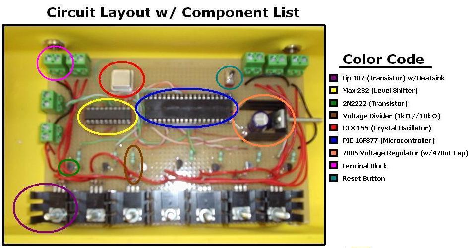
After deciding to use the Rule 360 GPH (gallon per hour) bilge pumps as our source of movement for our under water ROV, the next step was to design and build a circuit board that would be able to switch these pumps ON and OFF.
Since we are going to have a total of six pumps, two for forward, two for reverse, and two for surfacing we would need six switching circuits. Each circuit would control a pump of its own. We also wanted to implement a light that could be turned ON and OFF, but time and resources prevented us from completing that task. With the six pumps and light, we ended up building a total of seven switching circuits.
The Rule bilge pumps could potentially draw up to 3 amps; this was a problem because we were using a PIC16F877 microcontroller. This microcontroller can only source a few hundred milliamps, which is much too small. So the question was “What can we use to switch ON and OFF a large current?” Our answer to this was the TIP 107. The TIP 107 is a Darlington transistor pack, which means it is made up of two other transistors. With a heat-sink the TIP can handle up to 5 amps. This was perfect for the pumps.
However, we still couldn’t drive the base of the TIP with the micro-controller, there was still too much current draw on the PIC. To get around this, we biased the TIP with two resistors. We used a 1k-Ohm and a 10k-Ohm resistor in series creating a voltage divider. The resistors were able to handle the current needed to forward bias the TIP.
Now that we had the TIP in the ON position, we needed to be able to turn it OFF and then ON again. To accomplish this we used a 2N2222 transistor. The PIC can easily turn this ON and OFF, and in turn it will connect the voltage divider to ground, thus turning the TIP OFF and ON again. We also added a 470-Ohm resistor between the transistor and the PIC, this was to limit the current and protect the PIC from burning out.
We did run into a small problem after building our motor circuits. When we tried running the motors, instead of being able to switch a motor ON or OFF, they all ran constantly. We checked our solder joints and grounds, but everything looked to be okay. After we double checked our data sheets we finally realized that we had mixed up the collector and emitter leads on our TIP107 transistor. This was causing the current to flow constantly, which was why we weren’t able to switch the pumps ON and OFF. A quick solder job and a re-test, and everything was working as planned.
Now, to make the PIC work we had to use a CTX 155 crystal oscillator. This acts as the clock pulse for the PIC and runs at 4 MHz. We also used a 7805 Voltage regulator. We took a 9 Volt power supply that would run our external camera, and used it to power the 5 volt regulator at the same time. This meant we had 9 Volts going to the camera and 5 Volts going to the PIC.
The last chip we used was the MAX-232, this is a Maxim RS232 level shifter. Because the laptop’s serial port is a differential output, it uses positive and negative voltages to make the signal. However, the PIC chip is a TTL RS232 and can only handle 0 Volts or 5 Volts. The MAX chip converts them so that they can communicate without blowing things up. We chose this version because it required no external capacitors and would keep things much simpler.
The PIC chip is a microcontroller and has a built in EEPROM (Electrically-Erasable Programmable Read-Only Memory) and program memory. This made it easy to reprogram when necessary. It also has an 8-bit processor with 5 I/O ports.
After many hours of designing and soldering our circuit board was complete. We had seven switching circuits, six of them to run pumps, and an empty slot for a wildcard. Something like a light or emergency surfacing balloon could be implemented. There was also a voltage regulator to control the PIC and an external camera. The MAX 232 enabled us to communicate with a laptop, and the CTX 155 oscillator helped the PIC run smoothly. The rest was up to the software and mechanical development.
The PIC chip has a lot of free code space and open port pins for extra features. Features we would add include a water temperature sensor and a depth gauge. Another idea might be a device similar to an aerometer to gauge the speed of the sub. Perhaps a leak detector could be included to warn the controller of water intrusion.
No comments:
Post a Comment